Grooviks Cube
Introduction
I wrote this report post-event out of my memory as it is still relatively fresh and hasn’t quite evaporated into the vaults of my brain forever to remain hazy and altered. I’ll recall the events as they happened from my point of view, this is by no means an objective report of how the cube came to be. Sadly i did not have time to really blog the progress of the cube as it went along – i was far too busy fitting work, cube, moving house, and general BM prep all into 24 hours a day.
The first time I heard of the cube idea was probably from Barry just before the Whistler trip in 2009, I don’t know exactly where or when, it was at that point nothing then a fancy idea, amongst many others, to build a giant Rubik’s cube on the playa. I didn’t think much of it back then, as it was just another crazy idea amongst many which has been tossed around for some time. I had my own ideas concerning injecting a Meme into the Burn this year, and letting it evolve like a giant game of Chinese whispers, but i never quite figured out how to make that go in a practical sense even though i found the concept intriguing.
The idea for the cube was born during the new-years Whistler trip, which I missed due to being in German with Alissa and my parents, and was first suggested by Chris White, who ended up writing most of the software for the project.
Anyway, the topic came up again during the Febuary/March whistler trip, Barry, Chris, Mars and others had been starting to pour in more thought into it, imagining a large, scaffolding based structure, covered in fabric, 48ft high, lit up by lamps and gels. Emphasis was on “simple”. off-the-shelf parts only. My own thoughts started to engage in this – i realized this could become a very engaging project, maybe a unique opportunity to get involved in a very very large art installation with group more then capable of pulling it off.
In particular i recall standing in the kitchen with Barry during one of the many parties up in the Whistler cabin talking about possible ways to control the cube. We were imagining a controller standing in the center of the cube, thus being able to see all the sides of the cube. The problem with this was that it was too isolated an experience, only a single or very few people could stand in the cube, and the outside observers wouldn’t even realize that it was a human being controling the cube ! My thoughts started to ponder ways to make the experience wider, allow more players into the game and make it obvious how and who is controlling the cube. As always with ideas i just blurted out stuff as it occured to me – i said “what if we split the controllers into three parts”. Barry’s eyes lit up like – he said something like “oohhh that is EVIL – have one controller per axis!”. I think neither of us had any doubt at that point that we simply had to make this happen. The idea with the distributed controllers had, to me, elevated the project from a simple light sculpture, or even interactive light sculpture, into a enhanced version of a famous puzzle, one that required coorperation between multiple players and was much much harder then the original. I was sold.
Feasible or not ?
The last few days in Whistler my brain started to stir – i was starting to consider the ideas that had been thrown around and we started looking on the internet for parts, costs, figures and numbers. We set our budget was 10K- it seemed that despite the very short amount of time we had available we may be able to raise enough. Nobody questioned that we couldn’t do it for less.
The first few considerations involved establishing if we were at least int the right order of magnitude for this project to fly. Our initial, first design involved a tower, with a 24ft x 24ft base, 48 ft high, built out of standard scaffolding. It would be subdivided into cubies (the lingo didn’t exist at the time but cubie would later signify a single sub cube, with up to 3 facets on it ), each cubie would be 8ft x8ft8ft in size. The tower would have 6 8ft levels and be 3×3 cubies at the base. I started making some initial drawings:


The problem was that with the cube having one of it’s faces parallel to the ground, the opposite face would be impossible to see. We imagined having a plattform on top for this purpose, however it couldn’t be too large either or it itself would occlude that top face. Or maybe a seperate tower nearby ? That would be a major extra undertaking, to build another 45 ft structure ? At the time we were imagining the controller for the vertical axis to be sitting below the cube, with the other two controllers out, some distance at 90 degrees from each other. With the cube itself raised 16ft off the ground, they couldn’t be too far away or they would barely be able to see the bottom.
None of us had ever built anything even remotely of this size so we wanted to keep everything simple. Simple scaffolding, simple lighting, simple controllers and electronics. At that point we had only 7 months until the man would burn, so were really didn’t have time to make any custom manufactured stuff.
We started researching costs. Fabric and scaffolding were the first big unknowns. We established that fabric would be a limiting factor – with a cube 24ft on a side, we had an area of 3500 sq ft to cover. We found some information on a related project called the Tetrion (Large towers of scaffolding in the shape of tetris pieces, covered in fabric lit from the inside, which featured at the 2008 burn) which was very much along the same lines of what we were trying to do. We had worked out that they had used “Rosebrand stretch tendo”, a special, two stretch spandex material. Clearly their project had worked clearly this stuff was suitable for the playa. But we were looking at 2500$ minimum, just for the fabric. Looking at scaffolding, lighting and one idea included stretching the fabric, thus reducing the amount we needed considerably (by 40% or so!) but we didn’t know how much it would stretch. Scaffolding too started to explode in terms of cost but also in terms of manageability. 8ft spans are awkward to work with, since most people can only reach about 7ft with their hands. We could make the cube smaller, but then it would loose much of its impact factor. Barry insisted it should not be smaller then 15ft on a side. Reducing it to that size would slash material costs quite substantially, and maybe with the cube smaller we could add a new twist: putting the cube on its corner.
The Cube in the Sky
When we returned from Whistler in early March 2009 i began drawing various technical drawings of possible cube designs including the original design ideas with 8ft facets as well as several down sized versions with 6ft and 5ft basic lengths (cubie widths).

The first set of cube models we considered I also started toying with the idea of putting the cube on its corner. We had all agreed that that would be super cool but dismissed it as too difficult (remember we wanted to keep it all simple and off-the-shelf). I had looked at scaffolding types, one of which (Tube & Clamp Scaffolding) allows you to build practically arbitrary shapes. So I started thinking about the possibility of building a hexagonal base (The projection of a cube on its axis is a hexagon) to hold up the cube with its diagonal axis vertical. One design had the corner on the ground while the other had the lower corner about 8 ft off the ground.

Cube on it’s corner Visual Cube on it’s corner with an extra level This design had many desirable qualities, most importantly it would allow all sides to be visible from the ground. Further, it creates an obvious 3 fold on the ground, such that all the three axes of the cube have equivalent projections onto the ground meaning that the controllers could all be identical and just needed to be placed in positions 120 degrees apart. Aesthetically this was the right choice, and since we had, by this point, decided that we had to downsize the cube to 15ft from 24ft (halving costs of scaffolding and fabric if i recall correctly), we felt that we needed to add more spice instead. Putting the cube on it’s corner seemed like an appropriately mad challenge for this purpose.
While the electronics were being worked out I was iterating through various designs all of which had their advantages and disadvantages. The scaffold support structure under neigh the cube was annoying because of the additional scaffolding work, the optical occlusions and general messyness and because it was not clear how to ensure that the cube would be perfectly cubical and not warped. Another possibility that was suggested by a friend of ours who’s name i forget (Matt?) which was to build the cube out of EMT tubing with custom welded connectors. He then suggested putting the cube on an 8 ft post. Aesthetically this was very appealing, since nothing would occlude the cube.

Cube on a post ? I started running calculations on cost and feasibility. EMT is expensive, the tubing alone came to around 1000$, the connectors added another $600. Plus the daunting task of welding 64 custom connectors as well as a custom christmas tree like structure to run through the diagonal. All that with none of us having much experience with welding. I actually went to Home Depot to get some 1.5″ (or was it 2″ ?) EMT and tried finding metal tubing with the right outer diameter to slide in snuggly into the EMT. Fail. This turned out to be rather difficult. Plus the structure was getting rather expensive. Not getting a good lead on how to do this i returned to the scaffolding support and started making more detailed plans.Many features seemed unappealing as detailed above, but it seemed the only viable option at the time: Scaffolding was cheap to rent.

Planning in more detail where the scaffold tube would go and where people constructing it would stand. Until one afternoon I get a memo from Barry saying, come to Kevin’s House, he’s got a crazy idea for how to get the cube in the air. Kevin’s ingenious brain added an idea none of us had considered before, which was to hang the cube. His idea was to just lift the cube using a crane or fork lift. And leave the crane in place. Basically just have it hanging there. The big unknown was the cost of rental for such an opperation. While clever, the thought of having a crane there permanently was repulsive to me from an aesthetic standpoint since it would look like a failed or unfinished, rescued-at-last-minute art project (To my delight the crane turned out to be prohibitively expensive, unless we could get it from BM Org , which remained unclear till the end).
But the idea of hanging the cube was absolutely brilliant! I was sold. No visual obstructions, the cube could be built on the ground with easy access and then lifted into place ! So clean. So neat. We could build the cube out of lighter materials too! But what to lift it from ? Over the BBQ we talked about a number of possibilities. Theater truss ? That stuff can be rented, maybe we could build an inverted U to hang the cube from ? A bit of research quickly showed that a center hang of several thousand pounds required top end heavy-duty truss, esp when we’re talking about a 40ft span. Basically hanging the cube straight down was no an option, although aesthetically is was very pleasing. Hanging it from cables running from the tops of the vertical parts of the U would be an option but then the towers would need to be quite a bit taller so avoid very shallow hanging angles. All of this was not clicking into place and the costs for renting truss were out of bounds already.

This design was appealing but quickly turned out to be not to be practical Another idea was to reuse truss the we already had access to as a community. Eric Schurman had built a 70 ft tower out of radio towertruss in 2000, so he owned 7 10ft tower segments. I looked up the specs for the truss and did a number of buckling calculations and it seemed the towers were sufficiently strong in compression to hold up the cube.I spent several evenings working on a design, initially involving 3 50fttowers. Each tower would be guyed down to the playa by 3 steel cables. A4th cable would run to the center of the triangle, where the cube would be suspended from it’s top vertex. As before the problem was that to geta hanging angle of >60 degrees (thus avoiding ridiculous tensions in the cables as the force increases with the tangent of the angle and quickly runs of towards infinity as you approach 90 degrees) the towers had tobe quite a bit taller then the top of cube, which we wanted to be at37ft, leaving the bottom vertex 10ft off the ground. This however meant erecting 3 50ft towers (a daunting task in it self) and then raising a2500 lbs object in between them. Also it meant buying 8 more tower segments, at 140$ each. A minimum of 9 guylines were needed. All in all the costs were soaring up into the 2000-3000$ range, like, it seemed,every attempt i tried to lift this cube up in the air. Nothing was truly jumping out at me, and by this point we had considered at least 6 or 7 designs.

Three Tower Design - Note the three-fold symmetry and the UI stations, one for each axis. We liked this design a lot because it created an illusion of a 3D volume in which the cube was hovering as if by magic. At some point I was explaining my design ideas and worries design to Kevin. I was trying to explain how the guylines would run and i evidently didn’t do a good job. Kevin made some sort of suggestion that indicated to me he though the guy lines attached at the bottom of the cube, which was not what i had intended in my design. However this total mis-communication made me think: what if we attached the guylines say to the center of the cube ? That would make the towers smaller, because the point of attachment would have moved down by 13.5ft, so the towers could be 37ft tall.. well 40ft at least since the truss elements are 10ft long. So what if we moved them down even further ? The lower 3 corners of the cube make excellent attachment points (better then the center of the cube in many ways since the cables wouldn’t have to run through the cube). That takes the attachment down another 7 ft, so 30 ft tower would be sufficient!

Tensegrity Cube Design This design looked weird in many ways. The cube was suspended from below it center of mass, so I added three more guys from the upper 3 corners that run down directly to the playa. Essentially what this ended up as was a nice tensegrity style structure with the cube hanging in between three 30 ft towers held up by nothing but cables. Only two more 10ft tower segments would be required lowering the costs. Raising a 30ft tower is also much easier and can be done with simple manpower and without having a truck and a leverage arm. The guylines became considerably shorter. All in all i liked this design a lot. It appeared weird and impossible, and it had an inherent beauty. The three towers added a distinct three dimensionality to the whole object and increased its apparent size many times. The rigging was strange and unintuitive though. I looked through several books on tensegrity structures but in the end decided the most immediately useful thing would be to make a physical small scale model of the structure.
I built a small, cross-braced cube out of little pieces of dowel and erected three dowel towers on a thick plate of polystyrene that I found in Mark’s backyard. The towers were about about 8inches tall, and I guyed them down using string and rubber bands to adjust the tension, then the cube was suspended using more string. To my delight, once all the cables were tightened the cube appeared to be surprisingly stable. Because all the guys had rubber bands at one end (Another idea of Eric Schurman’s) it was easy to see where the structure took up most of the load when one pushed the cube around by hand.

Making physical models helped us get a feel for the mechanics and physics. This was the tensegrity model hung from 3 30ft towers and was our favourite model for quite some time, if it proved to be financially viable. Which sadly it did not. OK, so in principle this would work. Kevin and I started doing load calculations and wind calculations as with the prvious designs. This one was tricky though due to the sheer number of guylines. I made a highly simplified model and made a spreadsheet on google docs including little 2×2 and 3×3 matrix solvers that would calculate force-vectors given parameters such as windload (see wind load section) The question remained how the cube would be lifted into place and whether or not it would be taken down in a major windstorm, as we had intended for the hang-from-crane design idea. We tried a variety of different designs for the movable rigging (i.e. those guys that would be attached to winches), trying to avoid using too many block and tackles and winches since these turn out to be very expensive. Winches were necessary not only to get the cube up there but also to make it acessible in case some of the electronics broke.
Any design we came up with ended up with basic material costs in the 3000$ range, accounting merely for the basic materials (i.e. not accounting for many smaller components, shipping and the inevitable 50-100% overruns that tend to happen with project like this). I made a number of fairly involved wind calculations to access the tension in the guy wires. The problem was that the guys running out from the towers would take all of the weight (since it’s pulling the twoerrs inwards) plus any windload (particularily on the upwind side, but also, surprisingly, on the downwind side, becaues the cube is also tethered to the ground). The windload for a object of this size is substantial and in the order of 3000-4000 lbs in a 70 mph windstorm.
My calculations indicated that without wind, the load in the outer guys was about 1600 ( + pre-tension), assuming a cube wiehgt of 2000 lbs. At 4000 lbs horizontal windload, the guy load upwind was about 6600 lbs. While one can easily buy steel calble strong enough to hold this sort of tension, it was not clear what the anchor points could hold. Kevin was researching any available information on this but without any luck, except for wild guesses. Even from DPW we could find reliable figures, although we found out that they tend to use anchor screws like these which can hold 4000lbs – but in what sort of soil ? Is the Playa weaker or stronger then average soil ? (We found out much later on the playa that DPW infact uses these, and pulls one out of the ground every year using a crane to see what it can take. Apparently conditions vary significantly every year, due to weather effects over the previous winter, position of the city on the playa, etc, etc. Apparently they vary from 3000-8000lbs, this year it was on the higher end). Either way our working loads were uncomfortable close to what the anchors could take. One thought was to winch the cube down in case of wind, but this would be quite dangerous once the wind picked up above 30 mph and it would require maning around the clock with several people. Further costs were spiraling out of control and frankly we felt quite uncomfortable with a rigging project of this magnitude, with essentially zero experience in this field. I was starting to feel very uncomfortable about all this – we couldn’t find any design that was satisfying and within our budget and safe and our go-no-go deadline was approaching fast.
Barry, Kevin and I met up again to make a call on the tensegrity design. We went through all the calculation, Kevin checked the math, we talked about costs, rigging options, safety, operability, accesibility etc. Finally we came to a conclusion: Yes it could be done and no we won’t be able to do it given our budget & expertise.
So what do do instead. What about just building the cube out of scaffolding and putting it on its corner with guylines ? This would have an excellent visual effect, it wouldn’t require too much rigging, no cranes, it could be built on the ground ( The original reason for considering hanging desings). Barry was unsatisfied – he insisted the cube should be at least a little off the ground. We figured a small pedistool, say a few feet high, shouldn’t be much of a problem.
Aesthetics of Light
While the mechanics of the structure were still undetermined, we started to focus on the most important question – in fact our very first milestone: can we illuminate a panel of fabric, evenly, in bright and distinguishable colors, switchable by computer within a price and wattage range permissible by our budget ? We had set a hard limit on the date by which time had to have found a satisfactory solution or we could not go on.
Our first thoughts revolved around Halogen bulbs. Incancescent bulbs cannot be switched as much as we needed to switch them, and the possibility of using LEDs was quickly discarded due to being way out of our price range: We’d need either A LOT of them or special super-bright ones which were inherently expensive. We looked into LED panels or LED arrays but nothing we could find did what we needed for an acceptable price.
Halogen bulbs however are cheap. They can be switched relatively quickly. They have reasonably good life times. They’re bright. Theater gels are also cheap and come in all needed colors. Olli started researching and ordering various possible lights, from prefabricated, colored halogen bulbs to little, very bright and cheap stick light bulbs with custom made casings out of tin cans and gels attached to produce color.
Our first test at ATC (Barry & Heater’s old place) involved a piece of the aforementioned Stretch Tendo fabric, and a simple off-the-shelf 80W Halogen light. We attached the fabric in the door way and shone the light on it from about 8 ft away (at that point our imagined cube was still 24ft on a side). The results were mediocre. The biggest realization was that without massive amounts of diffusion between the lamp and the fabric, the light itself was always visible as a bright dot through the fabric reducing the apparent brightness of the fabric itself. Viewed from an angle (we ran up to the kitchen window one by one to get the appropriate angle, while someone blocked the direct line of sight to the lamp) the cloth appeared so much brighter. Diffusion however would loose a lot of the light intensity, shining it back into the cube.
Further we realised that light bleed was going to be a problem. Initially we planned to have little cones around each light, but due to the sheer width of the lamps (and we needed 6, not just 1) these cones needed to extend quite a long way into the cubie space before preventing significant light bleed into the next panels. In the corners this would quickly become prohibitive. Could we move the lights further back to make the cones narrower and thus sharper ? Not a lot, since the scaffolding would start to be in the way. With 100W bulbs, the brightness was acceptable but not great (provided we could somehow shield the direct sight of the lamp or diffuse it). That put us at 5600W without even considering computing or music, near 12000W if we went up to 200W. That would be a massive generator, one of those you tow behind a truck and a lot of fuel. A lot of fuel (Anyone have any figures on this ? ).
Switching the 110V, 100W bulbs was also a problem – that is finding a way for a central computer to control the on/off state of 54*6 = 324 lights. Mars had found something acceptable at whistler but at closer examination we found it to be way to expensive for what we needed.
Around that time (April 09) I had moved into a new place, “Danger House”, and started to get to know my new roommate, Mark Anderson, who happened to be working on a project for a Fire station i think, that involved a pretty glass sculpture and super bright LEDs. He clearly was an electronic wizard (and generally a genius). One night we were at our friend Mez’s house party (i forget the occasion) and we started brainstorming this lighting and switching dilemma we were facing. Mars was feverishly searching for possible solutions on the net (I think we were looking for sufficiently cheap Switching Relay Arrays at the time), – Barry was sitting on the bed looking deeply troubled. We were close to concluding that this cube project was in fact not achievable within the self imposed budget limitations (we were aiming for $10,000, with lets-be-honest-this-always-happens expected 100% overruns) Having exhausted my general, non-specific ideas I had little more to contribute, so I went to fetch Mark from the party to see if he had any bright ideas. I fail to recall all the excellent suggestions Mark made that night but the most important single thing he did was to convince us to put super bright LEDs back on the table.
He had just recently worked with this new type of LED unit (Luxdrive), which were available for around 15-20$ per RGB unit.
Luxdrive RGB ENDOR

The solution was to consider all the costs together: While considerably more expensive per light unit, using LEDs reduced costs in switching and in power consumption, cabling, fuel etc. Thus making the overall costs comparable to the halogen solution.
However the final convincing argument however was still to come.
The Day of Truth
The final decision on the lighting approach was approaching and by this point we had concluded to reduce the facet size to 5ft x 5ft and decided that the only way to prevent light bleeding was to subdivide the cube into little rooms, each with only a single outside facet. Originally we had thought of black cloth (cheap), thinking mainly about preventing light bleed, but someone suggested using mylar instead, a plastic foil type material with a aluminum coating (Aka PET film ).
Mylar Divisions It’s highly reflective (around 99% or so) and thus would increase our effective brightness, preventing diffusive loss into the cube. Olli and Matt (?) had build a protocube out of 1×2″ wood, measuring 5ft on a side and brought it to David Lockhart’s backyard garage (“The Bronze”). Olli had gotten a roll of mylar and a variety of halogen lamps, Mark had a bunch of LEDs with him. We glued mylar sides into the cube creating a kinked cone like structure inside and covered the outside with the spandex material we had ordered back in Whistler. We very quickly realized that the way to achieve even glow on the panel was to shine the light backwards onto the mylar which would then reflect the light back onto the panel. The lamp itself could then be occluded using itself or just some opaque disc. The results were stunningly better then the previous light tests and convinced us that the desired effect could, in fact, be achieved.
As for the light source, the brighter colors, such as red, yellow and white worked well with the halogens but the blues did not work at all. Turns out halogens have a weaker intensity in the blue part of the spectrum and filtering out the predominant portions with gels is far from trivial. In fact, by the time the gel is thick enough to leave only the blue portion, the intensity has dropped by 90% or so. In fact the “blue” was barely distinguishable from white. LEDs on the other hand have a narrow band emission spectrum and should thus have the edge when it comes to saturated colors. Mark held one of his blue LEDs (which by the way have 7WATTs and have to be mounted on a big aluminum plate to dissipate enough heat so they don’t burn through) into the proto-cube and we were all blown away by the sight. The picture below (taken on Barry’s iPhone) doesn’t do it justice – we were looking at a flat, bright, saturated deeply beautiful blue panel. The colors were rippling in a beautiful water-like pattern on the surface because the mylar would ripple and twist with every movement of the air. We were sold: LEDs would be the way forward – there was no question about that but it presented us with a challenge we had been trying to avoid all along: Having to build large numbers of custom electronics which had to be manufactured, tested and had to somehow withstand the conditions on the playa which are by no means electronics friendly.
Windloads
Building a 15ft x 15ft cubic object with an essentially wind impermeable surface clearly creates a significant force even in low winds. A quick look round the internet (e.g. Wikipedia on Drag Forces and Drag Coefficients ) gave a simple formula:
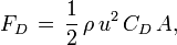
Fd is the drag force (Newtons) u is windspeed (meters/second) p is the density of Air (1.2 kg/m3 at sea level, so a little less at playa height) A is the cross-sectional area, normal to the wind.
and CD is the drag coefficient of the object in question. c accounts for the shape of the object and varies over at least 2 orders of magnitude from a sail shape to a fighter airplane or a fish.
Drag coefficients Drag coefficients It encapsulates empirically all the non ideal properties of the object in question, it’s shape, the amount of surface drag, turbulence etc. etc. etc. The whole formula accounts for both the pushing force the wind exerts on the frontal surface of the object as well as the suction effect that occurs on the backside of the object due to the low pressure region created. The latter can make substantial difference as can be seen by the different coefficients for say a flat disk (1.15) compared to a long cylinder (0.82).
A (smooth) cube has various coefficients (and cross sectional areas) depending on the angle of attack. Face on its close to 1.2 while on edge its only 0.8! Sadly I could not find any data what a cube head-on-vertex is, presumably a little less then the cube on edge, but not necessarily. Note that this all assumes smooth cubes! Our cube isn’t exactly smooth. But its also not super rough either, since the black spandex fabric was to keep all the holes closed and hugged the scaffold in soft outlines. And even if we knew the coeffcient for the cube, the coefficient itself depends on the wind speed and air density itself too (or rather on the Raynolds number), as object create considerably more drag force when the fluid flow is turbulent compared to when it’s laminar. Another scary factor is that, should one of the panels on the upward windside fail and rip, it would suddenly dramatically increase the wind coefficient, since the whole thing would act as a box kite. On the other hand, if this were to happen, most likely this would cause a cascade event ripping out further panels on the downwind side ultimately causing total destruction of the cube guts but in effect removing most of the wind load on the structure itself (it would be a giant 3D clothing line)
Summa summarum, the true coefficient for the cube in a 60mph windstorm could conceivably be anywhere between 0.8-1.2. I deceded to assume that it would be around .9 or so and engineer in generous margins into the guying design. I calculated the maximal cross sectional area as around 390 sqft, being exactly head-onto a vertex. On-edge the crossectional areas is less and exactly face on (impossible however in the orientation we intended for the cube) its 225sqft.
Note: A week or so before departure i checked the wind load calculations again for the millionth time and noticed i had made a mistake when calculating the maximal surface area: When sitting exactly on one vertex, none of the sideways pointing vertices point exactly at 90degrees to the ground, in fact they are about 19.5deg off, thus the actual maximal cross-sectional area is smaller then I initially worked with. I reanalyzed the cross-sectional aras again and in fact, depending on wind direction the cross-sectional areas would vary between 318 sq ft and 367 sq ft.
With all these parameters, the wind load in a 70mph wind then came out at around 4000 lbs of force, about as much as the cube turned out to weigh! I checked the figure against various sites and figures for sailing boat sails of the appropriate size (but with larger coefficients obviously, since there you want to catch the wind).
DISCLAIMER: I do not recommend using any of the calculations on this page for your own wind load calculations and neither I nor anyone ont he Groovik’s Team take any responsibility for its accuracy or suitablity for any purpose stated or not stated.
Wind Tunnel test
So by mid June 2009 we had the design of the cube fairly well established: ripstop fabric with grommets, attached by zipties to a scaffold frame. But would it stand up in one of the storms that typically rage over the black rock desert expanse ?
A static test with weight would be a possibility but it wouldn’t take in account the rattling and typical shock wind load behavior. Only a true wind test would be required – ideally a wind tunnel – but who’s got a wind tunnel in their back yar d? Well – if you can’t make the air move around a cube, you have to move the cube through the air – right ? . So on June 14th, some post-party Sunday, hungover and fueled by Burger King and Coffee, Barry and I drove Michael H’s truck out towards the mountains, loaded with a bunch of scaffolding, one of Eva’s proto-ripstop panels and a load of zip ties. More then one cubist and non-cubist thought this was a bad idea. Which is was. But not as bad as it was made out to
“…I am concerned about the safety of this idea. If there is a failure on the freeway, there is a substantial chance of injury or death. There are some things that make this in my opinion much more dangerous than its use on the playa …” E.S. 2009
Jesus Christ! We weren’t going to take it on the highway! We’re a little crazy but we’re not entirely barking mad ! Well, or maybe we are:


We found a reasonably quiet road off the main road and started assembling a scaffold cubie on top of Michael’s roof rack. It fitted perfectly. (Note, however, the assembly of spiky conducting pipes right under the high voltage over land line – clearly two science PhDs were at work here). People gave us the strangest looks as they passed in their cars. We then attached the panel and strapped the entire assembly to the lower frame of the car. What could go wrong ? With Barry driving the car and me hanging out of the front window with a camera in hand we hit the road, slowly increasing the speed. We had no idea how legal this was so we tried to get the thing over and done relatively quickly. It is quite surprising how much force even a 25 mph speed produces and how much that panel was buckling under the pressure. The grommets were being pulled through the fabric even just from the initial pressure the zipties were putting on it, but under the added tension they started tearing through the material. At about 48mph the panel ripped with a loud bang. The whole thing was extremely amusing and funny. And we took not a minute too long – after we had disassembled everything (which btw took 1/6th of the assembly time, a ratio that, interestingly, stood up for the entire structure on the playa) we drove back home, down our test route to the sight of 10 giant military trucks which had pulled up in the meantime, clearly intending to use the same stretch of road for their own practice run. I think they would have been rather surprised by a Truck with a scaffold cube strapped to the roof zipping past them at 50mph. We concluded that the fabric needed reinforcement, but not tooo much reinforcement (we wanted the fabric to fail at 70-80mph).
Driving the LEDs
Having made the decision to go forward with the super-bright luxdrive LEDS meant that we needed to build LED drivers. These are basically current regulators which keep the current below a maximum per LED and also provide the correct voltage drop from the supply voltage of 5V. The kind of LED we decided to use is new enough that few cheap off-the-shelf solutions exist although some do. Mark was able to find some for 15$ per channel, but we needed 56 * 3 plus spares which would come to 2500$, too much for our budget. Mark thus set out to design our own board, custom fabricated they would come to about 600$.
Luxdrive LED RGB units
Mark designed the board, made some proto boards using his inkjet printer, etched them and with Richard’s help started assembling it. Most of the components were SMD type components, which are considerably more tricky to solder, so we started training people to solder these. Olli, Maja and others were soldering test boards.

Richard discusses the printed circuit design
The central component of the board is a small integrated circuit, sadlyit was only available in XYZ packaging, which means that the 7 pins forthe package are not only surface mount style, they don’t even extendoutwards from the package, but instead consist of little pads on theunderside of the package.
This is the tiny central integrated circuit at the center of the original design. Note the lack of extended pins. This turned out to be the bain of Richard and Mark’s existence for about a month. By the end of June they had attempted to solder 6 boards, each with 3 channels – but only 1 or two boards ended up being functional, even after several soldering attempts on that central chip. Slowly but inevitably we concluded that while in theory manufacturable, the tiny component was not made for human manipulation.
We were stuck. We realized there was no way we could manufacture 54functional boards at a yield of 20% or so in less then a month.The LED heads themselves also turned out to be trickier to solder then imagined. Each head consisted of a 4×4″ aluminium plate with two luxdrive LEDs screwed to it (into predrilled and tapped holes), with wires soldered to the LED pads. Ash and Richard spent an hour soldering a single LED head. Thus that would mean another 120 man hours of work just for the LEDs.
Had we taken up a task to momentousness for us to achieve ? We had already overrun our planned go-no-go date by two weeks and due to long lead times on ordering the boards and some of the components which had to come from China (several weeks) our time was running out.

We called the critical meeting at ATC. The mood was mixed. On one hand we had made great progress, we has a design that was likely to work, in principle. Structure, fabric ,reflectors and UI stations had been prototyped successfully and in principle the electronics and lighting components had been too.On the other hand it was unclear we would be able to manufacture the electronic parts needed in less then 4 weeks leading up to August. We discussed the possibilities. We could simply continue, build as many light boards as we could and downsize the project as necessary – It would make a pretty light wall or a small chill space or something nice, even with as few as 10 working light panels. We had managed to create 2.5 working panels, surely we could make 10. This way would be rather unsatisfying but we could always return to the playa the year after with the full cube. In the mean time mark was working on another, potentially simpler to manufacture board, but we had no way of knowing if it would work. After all it had taken weeks to get the previous design working.Should we wait and delay the go decision another week giving him time to complete and test the design ? This would put the other areas of the project at risk, since parts couldn’t be ordered in time. But the small possibility of being able top manufacture all the boards due to an improved design was highly appealing. Furthermore, our funding situation had potentially improved by this point – it was looking likely that we could get fund matching from Microsoft and Google since the project was run through a non-profit organization (Shunpike). So with more money at hand, could we use the off-the-shelf solution ? It would put an extra $2000 onto our budget but maybe we could deal with that now. Or do we stop entirely, go to the burn with no art, have a good time,and build the cube for the year after ?

The mood in the room was somber. We voted on the options. Shakingly we decided to delay the decision one more week, wait for the results from Mark on the new board, risk the entire project but leave the chance of pulling the entire thing through and achieve the original vision.
My mood was incredibly stressed, i had trouble sleeping, couldn’t function at work, couldn’t think of anything useful and felt generally paralyzed.

Barry, Richard and Mathew discuss the first set boards fresh out of the oven.
Mark was working on designing a different board with a different central IC, which was not as suitable as the previously used component, but itcame in a package with actual pins and was thus much much easier to solder. However the new design was entirely untested and required extra components on the outside. There would not be enough time to get a proto-board etched, shipped, tested and the resubmit the final tweaked design. A simple, home-etched prototype worked, which gave us confidence but really we only had one shot at this.
Using the experience gathered from the previous boards Mark tweaked and tweaked the printed circuit design, trying to avoid areas which would form easy solder bridges, or bring parts in clashing distance. All of this had to be done theoretically, on the computer screen. I remember staring at the design on tuesday night at 2am, and ask naive questions and make naiive suggestions. Mark would think about it and either give me a solid answer or it would make him think about it and he’d adjust the design. Richard & Marked looked over the board some more the next day and then went for it, it was ordered.

Old board (left) new board (right)
Mark etched a protoboard and Richard was able to assemble it much easier then the previous design. All the channels works with less then half an hour of debugging! We had a working and manufacturable design. The one remaining question was thus whether or not we had to hand solder every board of if could mass produce them using a mask and oven procedure. The latter involves applying solder paste onto every solder pad, using a cut stencil, placing each component and then warming the entire board in an oven to a precise temperature, enough to melt that solder but not enough to damage the components. This is essentially the way commercial electronics is produced, except that the placing of the components is done by robots rather then humans. Still, this way of manufacture hugely reduces manual labor and more importantly reduced the chance of damaging components by touching them with the soldering iron for too long. While Mark has been trying o convert a toaster oven into a solder-melt oven using some custom thermostat electronics, Barry got a friend from Google involved in the project who had a lot of experience in producing boards in this way. Together they managed to get this process working for our board. Matt used his home-built laser cutter to produce a series of stencils for the solder paste. It took some time to get the thickness of the solder mask just right. Initially they were too thick and the components would flow away and twist as the solder melted underneath them.

The printed circuit board with solder paste applied.
As part of the enormous electronics manufacturing effort led by Olli (Many other components such as the power boards, LED heads and cables still had to be hand made) Matt, Richard, Becky and many others were able to manufacture all 65 boards (54 + spares) in less then two days ! Two days ! Matt spent many hours under the microscope checking the boards and repairing any incorrectly deposited components. The biggest electronics obstacle was overcome, with the quality of the final product exceeding our wildest dreams. In fact, only a single board broke on the playa, everything else worked solidly.